2N BlueStar/Stargate GSM Gateway
Installation Notes

2N BlueStar

2N StarGate
- The BlueStar supports 8 GSM boards (16 modules) and has an integrated Antenna splitter
- The StarGate supports 16 GSM boards (32 modules) and requires an external Antenna splitter
The following has been compiled from the 2N Docs, and experience from other Techs in the field.
Use your own experience to fill in the blanks and adapt the settings to your own unique installation.
Further information: BlueStar manual | StarGate manual | AT Commands | PRI config program | 2N Telecoms Wiki ![]()
Key Notes:
- AT commands: the serial data rate is 57600. When connected, enter the command: AT, and the CPU should respond OK.
To connect via telnet, the procedure is the same, except in PuTTY click Telnet and enter the CPU IP address. - Licenses: The initial license is only good for X amount of hours beginning when the ROM is placed on the CPU Card, not with power to the GSM. Typically, this license will expire before the equipment reaches the installation site. The first license will become invalid and a new license will be required after the X hours have passed.
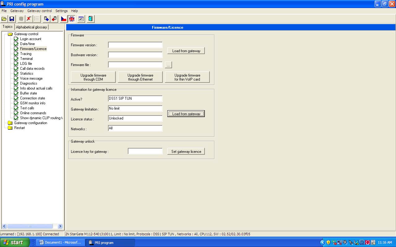
- Use the command ATI4 to print the factory number, which is required to obtain a new license. Or, in the configuration tool, goto: Gateway control ➤ Firmware / Licence : Information about gateway license, Load from Gateway.
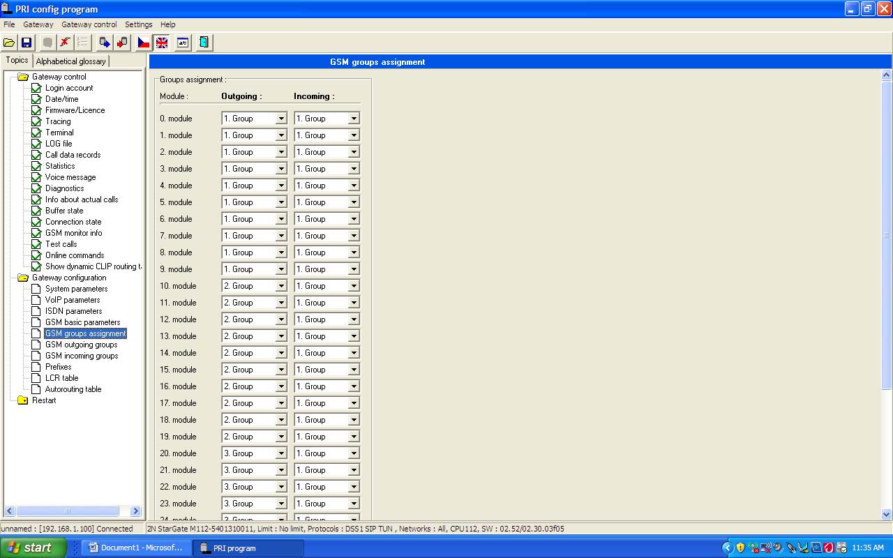
- SIM Cards: If you installing SIM cards from more than one cell carrier, make sure that they are separated in the gateway and control access in the PBX. By default, all SIM Cards are placed into Group 1 for incoming and outgoing calls. If Multiple SIM Card providers are used, a unique Group Id will need to be assigned to each carrier per GSM Card which has two modules. PINs MUST BE DISABLED ON ALL SIM CARDS OR ALL SIM CARDS MUST HAVE THE SAME PIN!
- Check SIM credit with the command at&gXX=XTDussd, where XX is the GSM module and ussd the command.
Example: to check the credit on gsm module g08, the command is *101#, enter the following: at&g08=XTD*101# - Fiber Transceivers: Multi Mode SC 4048 Transceivers are designed specifically to work with 2.0 Meg PRI circuits with out-of-band signalling (a D-channel). All other Media Transceivers will not work.
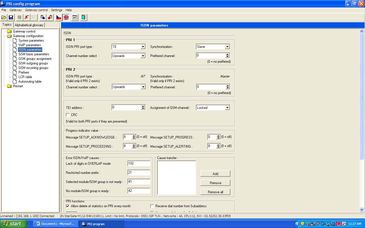
- PBX IS NETWORK (MASTER) if the GSM E-1 shares a cabinet with an E-1 that is connected to the local PTT, or other E-1 clocking source, GSM IS TERMINAL EQUIPMENT (SLAVE). Typically, two fields must be changed on the GSM gateway for the span to come up: "ISDN PRI port type: TE", and "Synchronization: Slave".
- Test calls: connect a headset to the AUX interface. For example, to dial the number 741111111:
- Via LCR settings, route the call through LCR: AT!SG32= 9741111111
- To call through the first GSM module directly: AT!SG0= 741111111
PRI board:
The PRI RJ45 uses standard pairs 1 (pins 1&2) and 3 (pins 4&5). Transmit and receive pairs can be swapped by moving the TE/NT jumpers at JP2 & JP3. Note, these jumpers change only the pairs, the USR/SLAVE setting is done on the ISDN parameters screen.
| Terminal (TE) mode: | Pair 1 - RX | Pair 3 - TX | The gateway is set to USR/SLAVE, the PBX is set to NET/MASTER. |
| Network (NT) mode: | Pair 1 - TX | Pair 3 - RX |
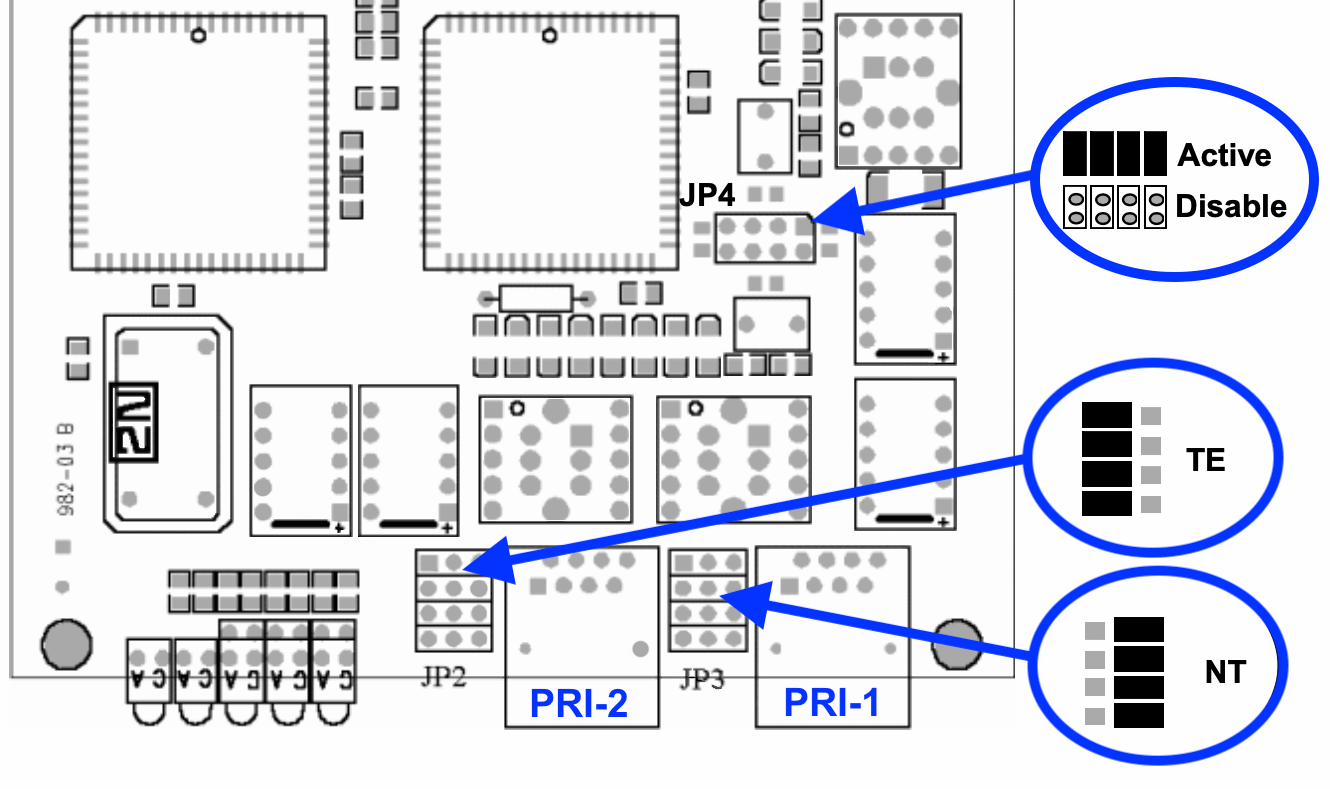
Jumper JP4 activates/deactivates a back-up connection between PRI1 and PRI2 when the system is switched off, or the PRI board is faulty. By default, jumper JP1 is disconnected, jumper JP2 is connected as TE, jumper JP3 is connected as NT and JP4 is connected.
The front panel Layer 1-3 LED's indicate the following status:
| Layer 3: | Active call | No active calls | |
| Layer 2: | Established | Not established | Establishing |
| Layer 1: | Synchronized | Disconnected | Synchronizing |
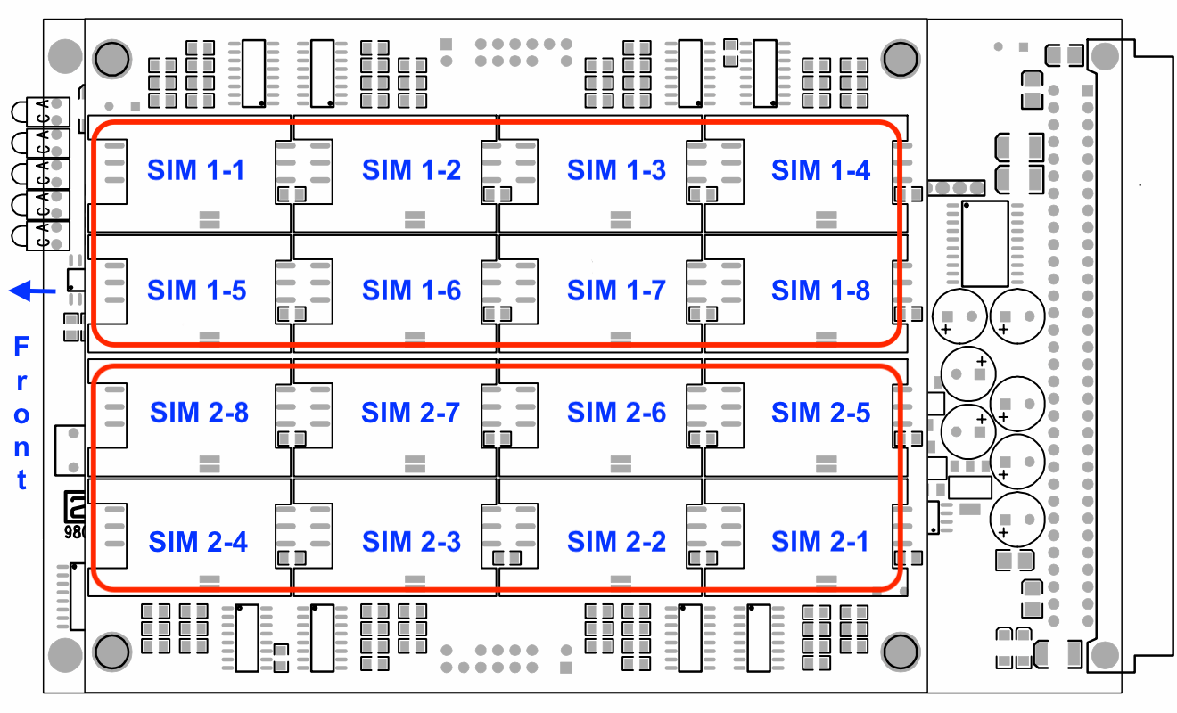
GSM board:
Each GSM board contains two GSM modules, each supporting up to 8 SIMs, though only one SIM card is connected to each GSM module at a time. Populate positions 1-1 (top left) and 2-1 (bottom right) to use both GSM modules with one SIM each.
The front panel GSM LED's 1 & 2 indicate the following status:
| GSM module idle | SIM card initialization |
| GSM module in use | GSM module blocked or initializing |
CS1000 Programming Notes:
1CLOCK REFERENCE
LD 73
(Normally already defined by the time the GSM is ready to be installed)
If there is NO clock reference set:
REQ PRT
TYPE DDB

CC DATA NOT 1.5MB

TRSH 00
RALM 3
BIPC 2
LFAC 3
BIPV 3 2
SRTK 5 30
SRNT 15 3
LFAL 17 511
SRIM 1
SRMM 2
2ADD PRI2 LOOP
LD 17
(Define LOOP number, and PRI CARD location)
PRI2 MG_CARD
041 000 0 01
3BUILD D-CHANNEL
LD 17
(GSM E-1 is in a cabinet with a PTT E-1 clocking from the Central Office)
TYPE ADAN DCH 12
ADAN DCH 12
CTYP MSDL
MG_CARD 000 0 01
PORT 1
DES GSM
USR PRI2
DCHL 41
IFC EURO
CNTY NET
PINX_CUST 0
CLID OPT1
CO_TYPE STD
SIDE NET
4Build Network
LD 15
(More than likely already programmed)
TYPE: NET
TYPE NET_DATA
CUST 0

TYPE NET_DATA
CUST 00
ISDN YES
5Build Trunk Route
LD 16
Build multiple routes for each SIM carrier
TYPE: RDB
CUST 0
ROUT 41

TYPE RDB
CUST 0
ROUT 41
DES GSM
TKTP TIE
DTRK YES
DGTP PRI2
ISDN YES
 MODE PRA
 IFC EURO
 CNTY NET
PNI 00000
ICOG IAO
ACOD 84
CDR YES (Respond to all CDR related prompts)
6Build Route Trunks
LD 14
Build as many trunks as you have SIM cards
TYPE: TIE
TN 41 1
DES GSM
TN 41 1
TYPE TIE
CUST 0
TRK PRI2
PDCA 1
PCML A
NCOS 0
RTMB 41 1
TGAR 0
CLS UNR DTN
7 Route calls to the Gateway
LD 90
Build or modify SPN for Mobile Phones
FEAT NET
TRAN AC1
TYPE SPN
SPN 032
FLEN 0
RLI 3
LD 86
Modify Route List Block
FEAT RLB
RLI 3
ENTR 0
ROUT 41
FRL 3
GSM Gateway settings:
Connect a 9-pin serial cable (crossed) between the CPU board and a PC running the Stargate PRI config program.
Goto Settings ➤ Communications settings and set the Communications type to Serial.
1Licence information
|
 |
| 2Active PRI state | 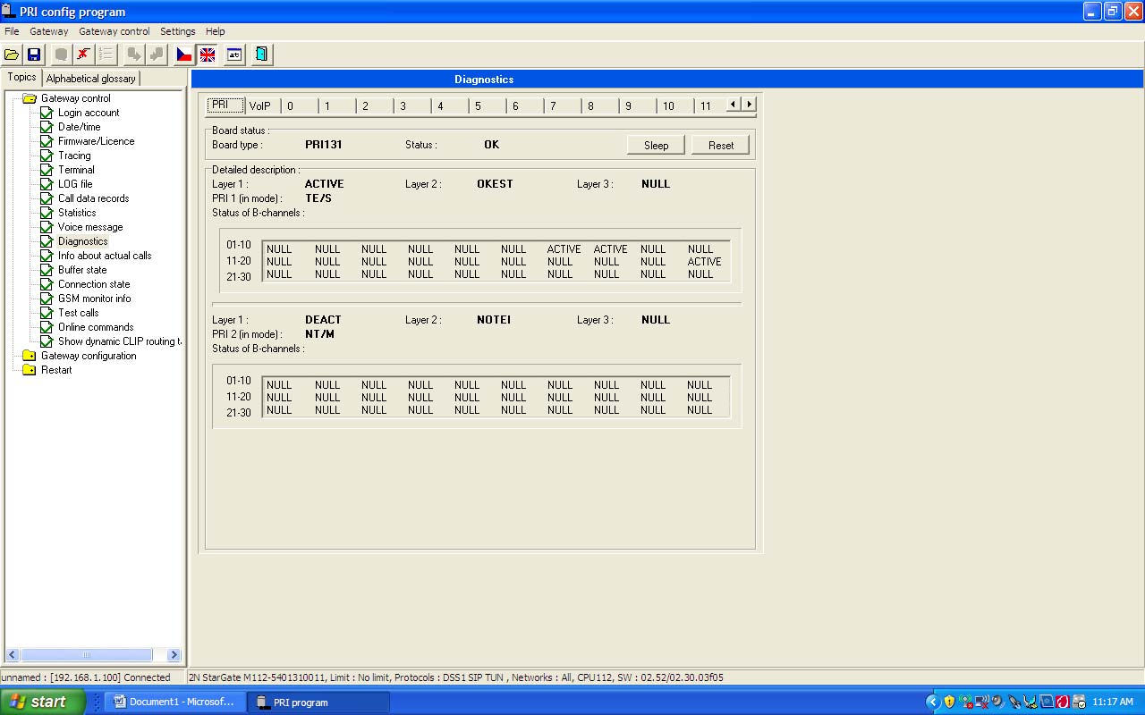 |
3Diagnostic
|
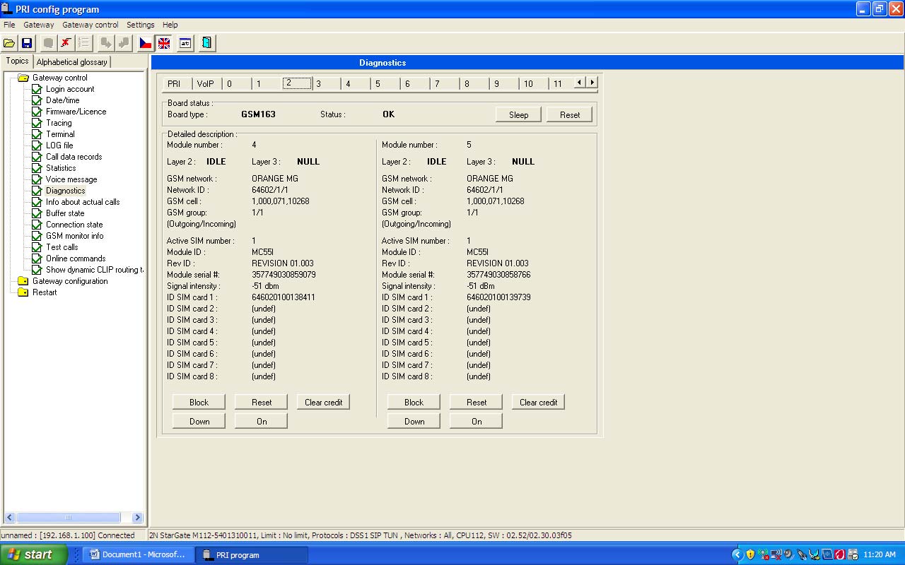 |
4Diagnostic
|
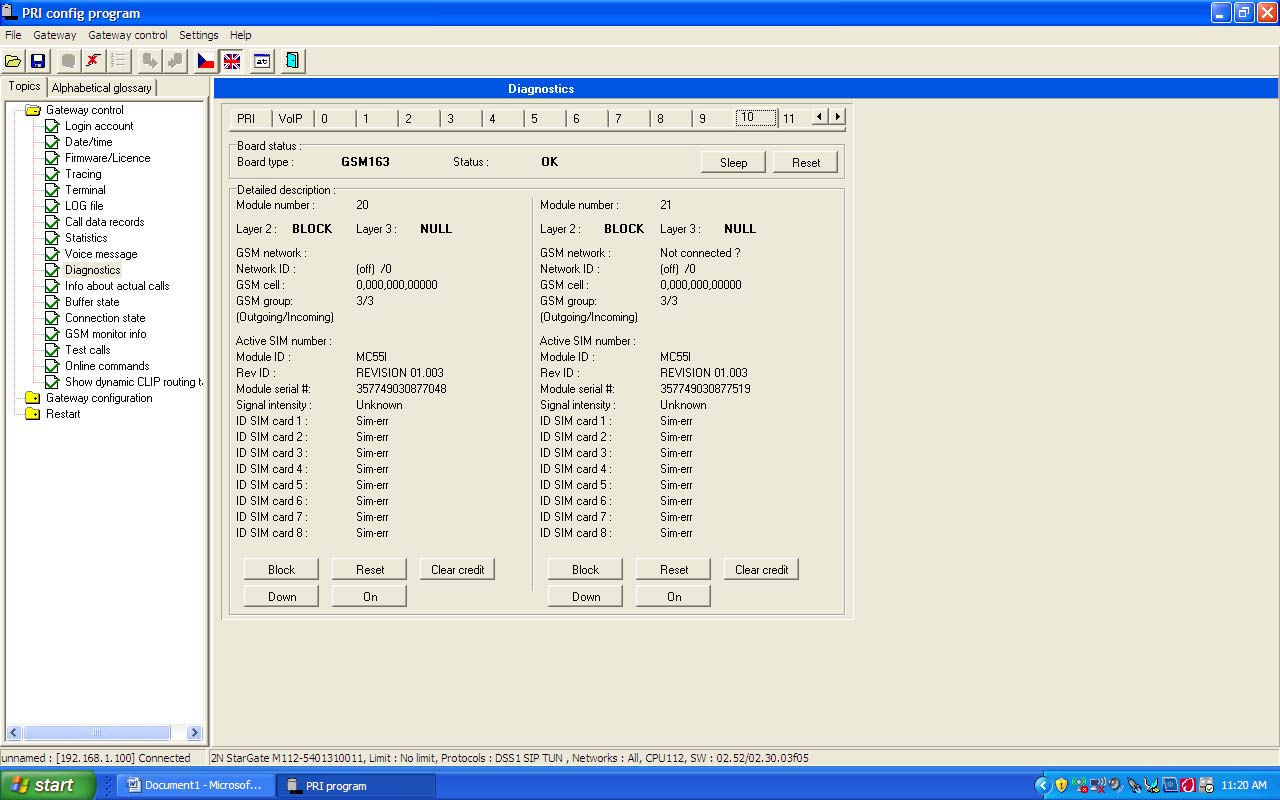 |
5Test calls
|
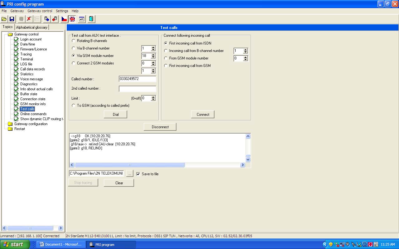 |
6System Parameters
|
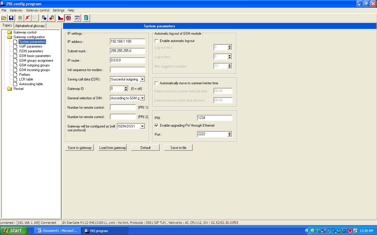 |
7ISDN Parameters
|
 |
8GSM Group Assignment
|
 |
| 9Active PRI state |  |
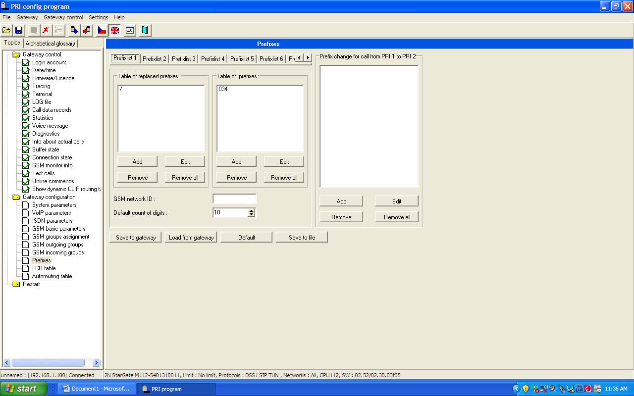
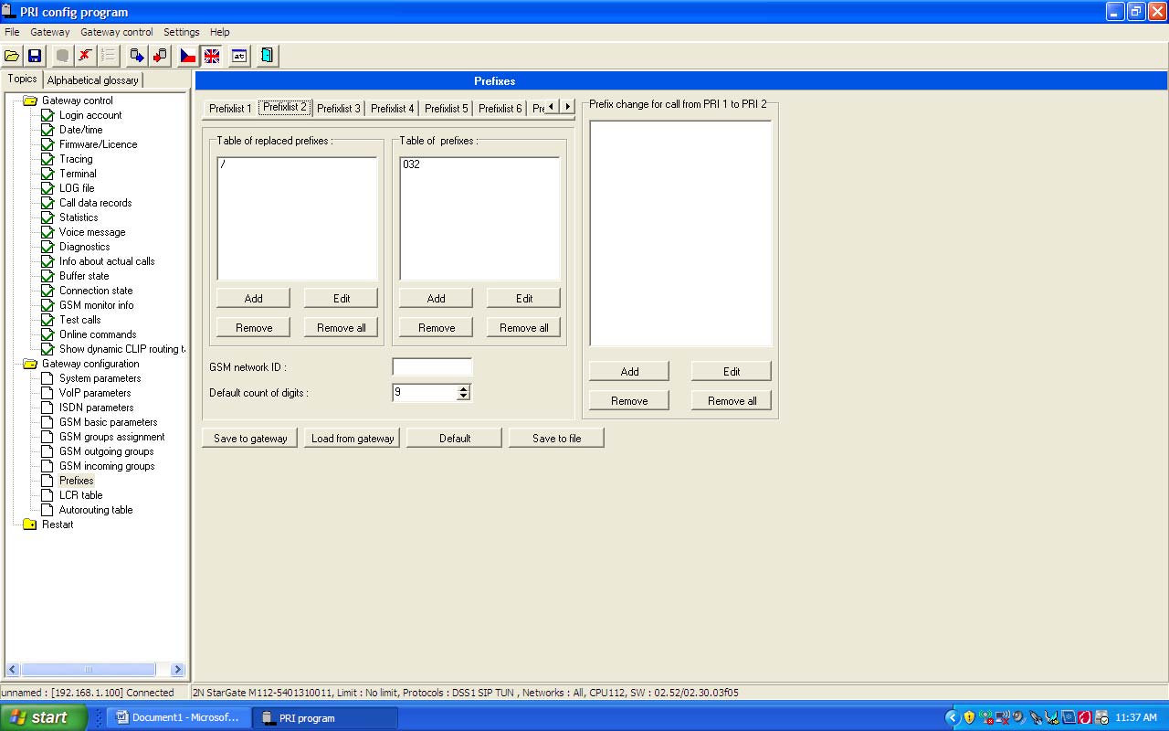
10Prefixes
|
 |
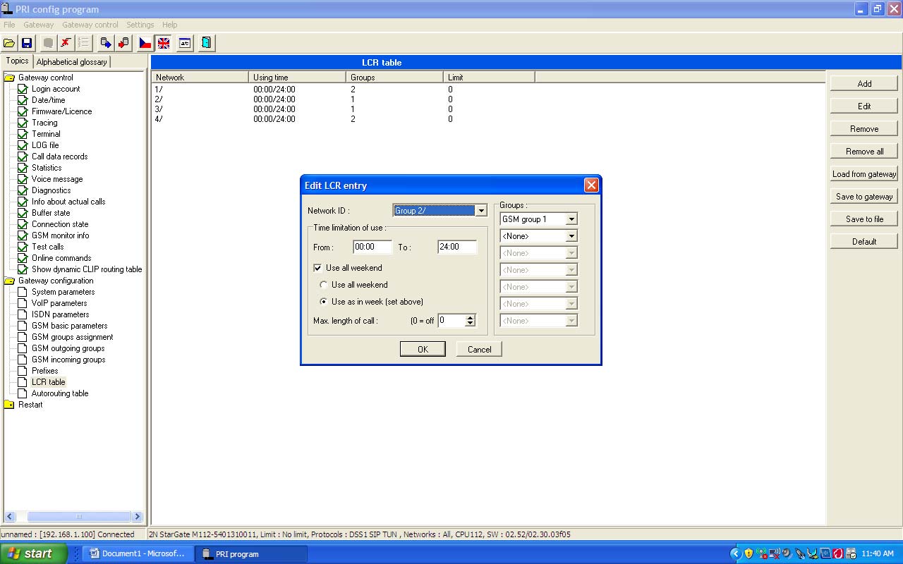
11LCR Table
|
 |
12Prefixes
|
 |
13LCR Table
|
 |