Load CPPM Sig-Servers (5.5)

A CPPM card (NTDW61, NTDW99) can function as either a Call Server or Signalling Server.
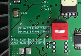
When deploying as a Signalling Server, equip the card with 2GB RAM, and a hard drive kit. Confirm the CSEL jumper (S5) is in the HD MASTER position: C2 (left down) to enable it.
Hard drive kit NTDW6102E5 comprises a 40GB IDE hard drive with four screws.
Ensure the drive jumper is in the cable select (CS) position before mounting.
A 'Leader' Signaling-Server is always required, though two servers may be installed in a load-sharing redundant configuration (one leader and a follower) for higher reliability.
The following applies to the CPPM (with hard drive) signaling server.
A Signaling Server does not require a security device or keycode.
Load 'Leader' Sig-Server
Put the installation software in the front panel slot, and boot from it.
Remember to Press F to force board to boot from faceplate drive.
CS 1000 Signaling Server Software Install Tool (sse-5.50.12)
============================================================

         #####
       #########   ########
      ########`` `#############
     ########      ``    `#############
    #######`         ######```####
    #######      ######``     `###
   #######    #####``          ####               NORTEL NETWORKS
   ####### #####`              ####
   `#########`                ####`    Communication Server 1000 Software
    #######`                 #####
    `#######               #####`               Copyright 2002 - 2008
    ##########            `###`
   ##``##########            #
  ##   `########################
  `#     `########################
    ###########################``
     `````````  ````####````

Please press <CR> when ready ...
When the main menu appears, select the tools menu and re-partition the CF.
From the MAIN MENU, select:
- <t> - To go to the Tools Menu.
- <b> - To re-partition and re-initialize the hard disk.
- <a> - Partition and initialize the hard disk.
The various filesystems are created, and the card will reboot.
- Remember to Press F to force board to boot from faceplate drive.
From the MAIN MENU, select:
- <a> - To perform a complete installation/upgrade (Signaling Server s/w, Internet Telephone f/w, etc).
- <y> - Yes, Do the Dependency Lists installation.
- <y> - Yes, start complete installation.
- <b> - Continue without restoring the IP configuration.
- Confirm/re-enter the IPMG location for this CPPM.
- <a> - Set this Signaling Server as a Leader.
- <a> - Co-resident (LTPS/VTRK/NRS).
- <a> - H.323 Gatekeeper and SIP Redirect/Proxy Server.
- <a> - Primary (Network Routing Service type for this server).
- Enter the networking parameters.
A summary screen is displayed, for example:
You have entered the following parameters for this Leader SS :
                (Press <a>-<l> to correct, <y> to proceed, <n> to reconfigure all.)

        Please enter:
<CR> -> <y> - Yes, these parameters are correct.
        <n> - Re-enter all of the parameters

        <a> - Node ID           : 1015
        <b> - Hostname          : PBXBOOK_LDR
        <c> - ELAN IP           : 10.10.10.15          eg, ELAN network = 10.10.10.0/24
        <d> - ELAN subnet mask  : 255.255.255.0
        <e> - ELAN gateway IP   : 10.10.10.254
        <f> - TLAN IP           : 10.10.11.15          eg, TLAN network = 10.10.11.0/24
        <g> - TLAN subnet mask  : 255.255.255.0
        <h> - TLAN gateway IP   : 10.10.11.254
        <i> - Node IP           : 10.10.11.17
        <j> - Call Server IP    : 10.10.10.5
              NRS configuration : Alternate GK + SIP
        <k> - Primary NRS IP    : 10.10.11.15
        <l> - Alternate NRS IP  : 10.10.11.16

        Enter Choice>
Review the entries, if all are correct, press <y> to proceed, otherwise enter a letter to correct.
- Make a note of the hardware ELAN MAC address which is displayed, as this may be required later.
When the installation is complete, an INSTALLATION STATUS SUMMARY is displayed. Confirm everything is OK!
Press <CR> to return to the Main Menu, and enter <q> to quit.
- The card will reboot. Do not press F, as the installation is complete!
Load 'Follower' Sig-Server
Put the instllation software in the front panel slot, and boot from it.
- Remember to Press F to force board to boot from faceplate drive.
When the main menu appears, select the tools menu and re-partition the CF.
From the MAIN MENU, select:
- <t> - To go to the Tools Menu.
- <b> - To re-partition and re-initialize the hard disk.
- <a> - Partition and initialize the hard disk.
The various filesystems are created, and the card will reboot.
- Remember to Press F to force board to boot from faceplate drive.
From the MAIN MENU, select:
- <a> - To perform a complete installation/upgrade (Signaling Server s/w, Internet Telephone f/w, etc).
- <y> - Yes, Do the Dependency Lists installation.
- <y> - Yes, start complete installation.
- <b> - Continue without restoring the IP configuration.
- Confirm/re-enter the IPMG location for this CPPM.
- <b> - Set this Signaling Server as a Follower.
- Enter the host name of the Leader, eg: PBXBOOK_LDR.
CS 1000 Signaling Server Software Install Tool (sse-5.50.12)
============================================================

This Follower Signaling Server will obtain its data network and IP
telephony configuration from the Leader Signaling Server at boot.

To identify this Signaling Server, please enter a Hostname.

Hostname : PBXBOOK_LDR
The card will later use BOOTP to retrieve it's configuration from Element Manager.
- Make a note of the hardware ELAN MAC address which is displayed, as this will be required later.
Introduce the Follower to the Leader
Open Internet Explorer and bookmark Element Manager. Then login...
- User Id: admin1 / admin2
- Password: 0000
- Click IP Network ► Nodes: Servers, Media Cards
- At Node Configuration, click Import Node Files
- Enter the Leader Signaling Server's ELAN IP address
- Click Import - the config files are retrieved, and the page refreshed
- Click Edit next to the Node where the server is to be added
- Click Add next to Signaling Servers
- Click Signal Server 0.0.0.0 Properties
- Enter the Follower server details:
- • ELAN IP address, and MAC address

• TLAN IP and Gateway IP address's
• Hostname, eg: PBXBOOK_FLWR - • ELAN IP address, and MAC address
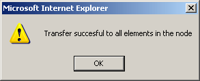
- Click Save and Transfer, and OK.
The transfer process begins. It will fail - but don't worry! - Press the Reset button to reboot the Media Gateway
- Save and Transfer again. This time it shouldn't fail!