Installing a VGMC (MC32)
Installing and Programming a 32 Port Media Gateway Card
- Seat the MC32 VGMC card in a free slot. It's similar to a MIRAN card, but with 32 ports.
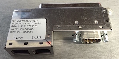
- Plug the ITG card adaptor (A0852632) into the corresponding card slot Amphenol.
- Run two patch cables from the RJ45 Jacks on the ITG card adaptor to the data switch.
Note, the top RJ-45 connector is ELAN, the bottom RJ-45 is TLAN.
- Log in to Element Manager.
- Select IP Telephony ► Configuration from the left menu
- From the Node Configuration screen, click Edit next to the Node ID
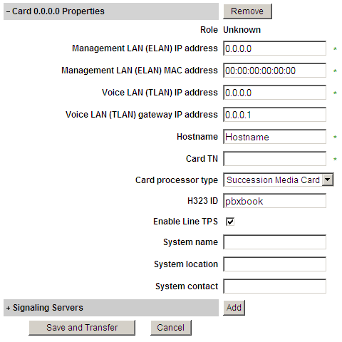
- Click on the ADD button, located next to the Cards option.
- Enter the following:
- ELAN IP address
- ELAN port MAC address, printed on the faceplate label
- TLAN IP address
- TLAN gateway IP address
- A Host Name, eg: VGMC_1
- The TN (l s c), where the card is located
- Hardware type, eg: Succession Media Card
- Click Save and Transfer, and click OK
The transfer process begins. It will fail - but don't worry! - Press the faceplate reset button, and wait for the card to reboot.
- Click Save and Transfer again.
If successful, the configuration will transfer to the card.
Note: If this is a new card, you will need to build the Voice Gateway Channels in LD 14.
Replacing a 32 Port Media Gateway Card
- Log into PBX, and enter LD 32
STAT l s c u. If the card is enabled, disable it withDISC l s c u- Remove the old MC32 card, and install the new MC32 card
- Log into Element Manager, and go to Node edit area where the card is. Open that cards info.
- Enter the ELAN mac address of the replacement card, printed on the faceplate label.
- Click Save and Transfer, and click OK
The transfer process begins. It will fail - but don't worry! - Press the faceplate reset button, and wait for the card to reboot.
- Click Save and Transfer again.
If successful, the configuration will transfer to the card. - Enable the card in LD 32:
ENLC l s c u
If it continuously fails...
If the front panel display hangs on T:20, the VGMC is not getting an (ELAN) IP address. The reason for this may be:
- The loadware version is wrong (CF card)
- The card is not set to follower/BootP mode
- The MAC address is wrong in Element Manager
Manually update the card:
- Remove the VGMC, and remove the Compact Flash (CF) card on it. Using a CF to USB reader, mount the card on your PC.
- Locate the
IPLxxxxx.saloadware file in the root directory of the Signalling Server software CD, and copy it to the PC. - Rename this file
exec(no extension), and copy it to the CF, replacing the older version already there. - Put the CF card back on the VGMC, and reseat the card. Wait for it to boot, and subsequently respond to PING.
- If it's a new VGMC, try Save and Transfer again - if it's a replacement, it should now automagically register.
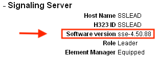
Use an IPLxxxxx.safile matching the Signalling Server version, which is found in Element Manager on the home screen after expanding "Signalling Server". Or copy theexecfrom an already installed/working card.
Set as "follower":
- Connect a TTY to the "Maint" port: 9600/8n1. The default password is: admin1/0000
- Enter the command
clearLeader. This makes the card a "follower", invoking BootP mode. - Reset the card using the front panel reset button. After a booting, the card should respond to a ping.
- If you are unsure about the cards MAC address, watch carefully for it during the boot sequence.
- The
itgCardShowcommand displays information about a Voice Gateway Media Card.
Reset the CLI username and password:
- Connect a TTY to the "Maint" port: 9600/8n1.
- Reset the card using the front panel reset button, and watch the TTY output.
- Enter
jklwhen prompted to enter the BIOS, note: there's only a six second window! - At the CLI prompt, enter the following command:
shellPasswordNvramClear - Type
rebootat the prompt to reboot the card. The default password is: admin1/0000
Erase all settings in NVRAM:
- Connect a TTY to the "Maint" port: 9600/8n1.
- Reset the card using the front panel reset button, and watch the TTY output.
- Enter
jklwhen prompted to enter the BIOS, note: there's only a six second window! - At the CLI prompt, enter the following command:
nvramClear - Type
sysRebootat the prompt to reboot the card.
Force 10 Mbps, Full duplex:
Sometimes auto-negotiate will not work, you will see the TLAN link light dropping, PING has only intermittent success.
IPL> tLanSpeedSet 10100         set speed to auto-negotiate ("10"= set 10 Mbps)
value = 40 = 0x28 = '('
IPL> tLanDuplexSet 0            enable Full-duplex mode ("1"= half-duplex mode)
value = 1 = 0x1
IPL> itgCardShow

      Index        : 0
      Type         : EXUT
      Role         : Follower
      Node         : 2869
      Leader IP    : 10.10.10.17
      Card IP      : 10.10.10.53
      Card TN      : 8 0 8
      Card State   : ENBL
      Uptime       : 0 days, 0 hours, 18 mins, 12 secs  (1092 secs)
      Codecs       : G711Ulaw(default), G711Alaw, G729A, G711CC, T38FAX
ELAN (ixpMac1) stat: 10 Mbps, Half duplex  (No Carrier)
TLAN (ixpMac0) stat: 10 Mbps, Full duplex  (No Carrier)      ◄ Full duplex set

value = 1 = 0x1
IPL>
Now, force the associated ERS TLAN port to 10 Mbps, and full-duplex.
Passwords:
- If the card is new (out of the box), then the user ID is admin1 and the password is 0000.
- If the card previously connected to a Call Server, then the user ID and password are the PWD1 of that Call Server.
- If the user ID and password are not known, use the procedure above to reset the IPL> CLI Shell username and password.


