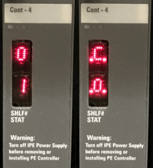
NT8D01 Controller faceplate codes
The NT8D01 Controller faceplate has a two digit hexadecimal display with two modes: normal operation and power-on-reset/self-test.

Normal operation
During normal operation the display alternately shows:
1. The Controller number (1-95) in hexadecimal.
2. The Controller tracking mode (port on which the Controller clock is tracking), indicated by decimal points. The possible tracking modes are:
- C0 - Controller is tracking to the network connected to port 0.
- C1 - Controller is tracking to the network connected to port 1.
- C2 - Controller is tracking to the network connected to port 2.
- C3 - Controller is tracking to the network connected to port 3.
- CF - Controller is not tracking any network, or not connected.
eg, Controller #1, with a superloop connected to port 0: display alternates 01 and C0.
Superloop (SUPL) and controller (XPE) assignments are printed and programmed in LD 97 (admin),
or printed and STATed in LD 32 (maintenance). See below...
Maintenance
If you suspect a bad loop, but the NT8D04 (superloop) is OK, try moving the CONT-4 back plane connector to one of the other ports. They are marked SL0, SL1, SL2 and SL3 - only possible with 1 Superloop/IPE. Re-enable the Superloop and XPEC (LD 32), and test.
Remember, controller cards are not hot swappable: always disable the superloop, and power off the IPE shelf before removing one.
See LD 32 for the following commands:
| Command | Description |
|---|---|
| STAT sl | Get status of specified superloop |
| DISL sl | Disable specified superloop |
| DSXP x | Disable Controller x and all associated IPE cards |
| ENLL sl | Enable specified Superloop |
| ENXP x | Enable Controller x and associated IPE cards |
| XNTT sl | Do self-test of Network card for specified superloop |
| XPCT x | Do self-test on Controller x |
| XPEC (x) | Print data for one or all Controllers |
| SUPL (sl) | Print data for one or all superloops |
Also see LD 30 for the following commands:
| Command | Description |
|---|---|
| CPED l s | Clear Peripheral Controller maintenance displays |
| RPED l s | Read Peripheral Controller maintenance displays |
The 16 most recent displayed codes, stay in memory and can be reviewed using LD 30: RPED l s.
Self-test codes
During the self-tests, the display quickly shows the self-tests listed below. If a test fails, the display shows the number of the failed test for 0.5 seconds before continuing the remaining tests. The self-test sequence is repeated until all tests pass, so a faulty card will cycle.
| # | Definition |
|---|---|
| 02 | A31 #1 external buffer test. |
| 03 | A31 #1 internal context memory test, phase A. |
| 04 | A31 #1 internal context memory test, phase B. |
| 05 | A31 #1 internal TXVM memory test. |
| 06 | A31 #1 configuration memory test. |
| 07 | A31 #1 external FIFO test. |
| 08 | A31 #2 external buffer test. |
| 09 | A31 #2 internal context memory test, phase A. |
| 0A | A31 #2 internal context memory test, phase B. |
| 0B | A31 #2 internal TXVM memory test. |
| 0C | A31 #2 configuration memory test. |
| 0D | A31 #2 external FIFO test. |
| 0E | peripheral side W72 loopback test using A31 #1. |
| 0F | peripheral side W72 loopback test using A31 #2. |
| 10 | R72 #1 N-P switching control memory test. |
| 11 | R72 #1 320 x 8 NIVD buffer test. |
| 12 | R72 #1 N-P quiet-code register test. |
| 13 | R72 #1 P-N switching control memory test. |
| 14 | R72 #1 640 x 8 XIVD buffer test. |
| 15 | R72 #1 640 x 8 XIVD loopback buffer test. |
| 16 | R72 #1 P-N quiet-code register test. |
| 17 | R71 #1 register test. |
| 18 | R71 #1 continuity test, peripheral side. |
| 19 | R71 #1 continuity test, network side. |
| 1A | R71 #1 simulation packet transmission test. |
| 1B | DUART port A self-test. |
| 1C | DUART port B self-test. |
| 1D | R72 #2 N-P switching control memory test. |
| 1E | R72 #2 320 x 8 NIVD buffer test. |
| 1F | R72 #2 N-P quiet-code register test. |
| 20 | R72 #2 P-N switching control memory test. |
| 21 | R72 #2 640 x 8 XIVD buffer test. |
| 22 | R72 #2 640 x 8 XIVD loopback buffer test. |
| 23 | R72 #2 P-N quiet-code register test. |
| 24 | R71 #2 register test. |
| 25 | R71 #2 continuity test, peripheral side. |
| 26 | R71 #2 continuity test, network side. |
| 27 | R71 #2 simulation packet transmission test. |
| EE | Bus error, exception errors, etc. |