51,61,81 Block Diagrams
Meridian large system components and logical connections:
Option 51C:
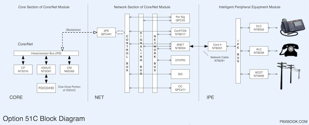
The Option 51C has a single Core/Network module, supporting a Half Network Group (16 Loops, 0-15). The core is not redundant. PRI/T1 cards go in the Network section of the Core/Net module.
Intelligent Peripheral Equipment (IPE) modules contain the station and analog trunk cards (anything with a TN). IPE Modules are standard.
Full size: Option 51C ![]()
Option 61C:
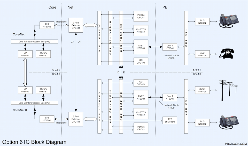
The Option 61C adds a second Core/Network module for core redundancy, and expands the system to 1 Full Network Group (32 Loops, 0-31). The two cores are connected via an "interprocessor bus". As with the 51C, PRI/T1 cards occupy a loop slot in the Network section of the Core/Net module.
Shelf 0 and 1 Control Bus's are connected via J3 and J4 from the 3 Port-Extender cards (3PE), and not via A,B,C cables as with the Option 81C.
Full size: Option 61C ![]()
Option 81C:
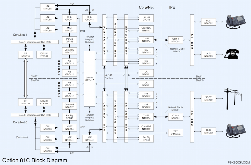
The Option 81C, with IGS, supports up to 5 Network Groups 0-4 (160 Loops, 0-159). The diagram shows two Network Groups: 0 and 1. ABC cables are used to connect the Control Buses in each group.
From Release 25, a dual-ring Fiber Network may replace the older IGS (intergroup switching) cards and module, expanding an Option 81/81C from 5 to 8 network groups, or from 160 to 256 loops. A NTRB33 FIJI card is installed in each Core/Net or Network module (not shown).
Full size: Option 81C ![]()
Click image to view, or right-click and select "Open Link in New Window/Tab".
On the Buses:
No, not those buses, the system buses:
| Bus | Description |
|---|---|
| Network Bus | Voice and data time slots. For example, path for phone conversations, tones, and music on hold. |
| Signal Bus | Signaling state changes (eg. off-hook or dialing from IPE equipment) to Peripheral Signal cards. |
| Control Bus (24 bit) | Direct link from any network card to the Three-Port Extender (3PE) card in the same network group.
Used by the Peripheral Signal card to alert the Call Processor (CP) of changes in the signaling state. |
| Interprocessor Bus (32 bit) | Link between the active Call Processor (CP) and the other core components, eg. hard/floppy drive, etc.
Instructions to and from the active CP, pass through a CNI card in the Core, to a Network 3PE card. |
| IPE Bus | On the backplane of each IPE module, the link from the IPE cards to their Controller card.
From the Controller card, timeslots are sent to or from a Superloop card. |