IP Office Port Pinouts
Note: Throughout the following, Tx = from IP Office and Rx = to IP Office.
Analog Trunk Ports (RJ45)
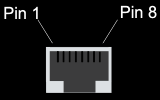
| Pin No. | Description |
|---|---|
| 1-3 | Do not use |
| 4 | Ring |
| 5 | Tip |
| 6-8 | Do not use |
Power Fail and POT Ports (RJ45)

| Pin No. | Description |
|---|---|
| 1&3 | Do not use |
| 2 | Connected to pin 6* |
| 4 | Ring |
| 5 | Tip |
| 6 | Connected to pin 2* |
| 7&8 | Do not use |
* Pins 2 and 6 are shorted together and, via a ‘ringer’ capacitor, connected to in 5.
DS/DT Ports (RJ45)

| Pin No. | Description |
|---|---|
| 1-3 | Do not use |
| 4 | Sig 1 |
| 5 | Sig 2 |
| 6-8 | Do not use |
ISDN Port - BRI (RJ45)

| Pin No. | Description | Signal Direction |
|---|---|---|
| 3 | Transmit Data (Tx-A) |  |
| 4 | Receive (Rx-A) |  |
| 5 | Receive (Rx-B) |  |
| 6 | Transmit Data (Tx-B) |  |
ISDN Port - PRI (RJ45)

| Pin No. | Description | Signal Direction |
|---|---|---|
| 1 | Receive (Rx-A) |  |
| 2 | Receive (Rx-B) |  |
| 4 | Transmit Data (Tx-A) |  |
| 5 | Transmit Data (Tx-B) |  |
LAN Port - 10/100 BaseT (RJ45)
For IP Office 403/406 the information below refers to LAN ports 1 – 7. Port 8 is switchable in software (exchanges Tx and Rx signals).
For IP412 and WAN3, both ports have the Rx and Tx connections exchanged.

| Pin No. | Description | Signal Direction |
|---|---|---|
| 1 | Receive (Rx-A) |  |
| 2 | Receive (Rx-B) |  |
| 3 | Transmit Data (Tx-A) |  |
| 6 | Transmit Data (Tx-B) |  |
DTE Port (25 Way or 9 Way D-Type socket)
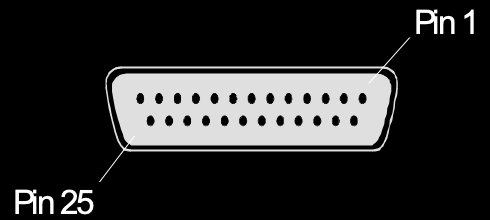
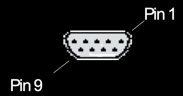
| Pin No. (25 Way) | Pin No. (9 Way) | Description | Signal Direction |
|---|---|---|---|
| 2 | 3 | Receive Data (Rx) |  |
| 3 | 2 | Transit Data (Tx) |  |
| 4 | 7 | Request to Send (RTS) |  |
| 5 | 8 | Clear to Send (CTS) |  |
| 6 | 6 | Data Set Ready (DSR) |  |
| 7 | 5 | Signal Ground | |
| 8 | 1 | Data Carrier Detect (DCD) |  |
| 20 | 4 | Data Terminal Ready (DTR) |  |
| 22 | 9 | Ring Indicator (RI) |  |
Audio Port (3.5mm Stereo Jack Socket)
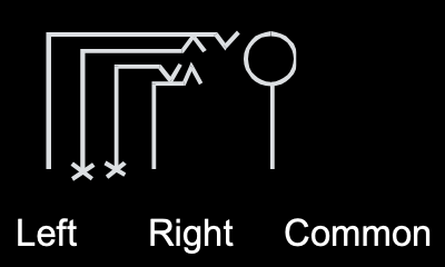
| Pin No. | Description | Signal Direction |
|---|---|---|
| Common | Common | |
| Left | Audio In - Left Channel |  |
| Right | Audio In - Right Channel |  |
Expansion Port (RJ45 Socket)

| Pin No. | Description | Signal Direction |
|---|---|---|
| 1 | Receive (Rx-B) |  |
| 2 | Receive (Rx-A) |  |
| 3 | Sync-B |  |
| 4 | Clock (Clk-B) |  |
| 5 | Clock (Clk-A) |  |
| 6 | Sync-A |  |
| 7 | Transmit Data (Tx-B) |  |
| 8 | Transmit Data (Tx-A) |  |
| Shield | Connected to chassis | Ground |
External Control Port (3.5mm Stereo Jack Socket)
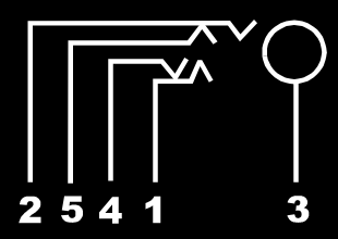
| Pin No. | Description |
|---|---|
| 1 | Circuit 1 |
| 2 | Circuit 2 |
| 3 | 0 Volts (Ground/Chassis) |
| 4 | Not Connected |
| 5 | Not Connected |
| Control Circuit | Information |
|---|---|
| Control Circuit 1 | Pin 2 & 3, ensure that Pin 2 is at a positive voltage with respect to Pin 3. |
| Control Circuit 2 | Pin 1 & 3, ensure that Pin 1 is at a positive voltage with respect to Pin 3. |
Each circuit can be switched independently.
| Switch Setting | Information |
|---|---|
| ON | Low resistance between Pins. |
| OFF | High resistance between Pins. |
WAN Port (37 Way D-Type Socket)
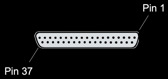
| Pin No. | Description | Signal Dir. | Pin No. | Description | Signal Dir. |
|---|---|---|---|---|---|
| 1 | V11 Rx-B |  | 20 | V11 Rx-A |  |
| 2 | V11 Ind-A |  | 21 | V11 Ind-B |  |
| 3 | V11 Clk-A |  | 22 | V11 Clk-B |  |
| 4 | V11 Tx-A |  | 22 | V11 Tx-B |  |
| 5 | V11 Ctl-B |  | 24 | V11 Ctl-A |  |
| 6 | V11 Gnd | 25 | WAN ID 0 |  | |
| 7 | WAN ID 1 |  | 26 | V24 Tx |  |
| 8 | V24 DTR |  | 27 | V24 RTS |  |
| 9 | V24 Rx |  | 28 | V24 RxClk |  |
| 10 | V24 TxClk |  | 29 | V24 RI |  |
| 11 | V24 DCD |  | 30 | V24 DSR |  |
| 12 | V24 CTS |  | 31 | N/C | |
| 13 | N/C | 32 | V35 Tx-A |  | |
| 14 | V35 Tx-B |  | 33 | V35 SCTE-A |  |
| 15 | V35 SCTE-B |  | 34 | V35 Gnd | |
| 16 | V35 Rx-B |  | 35 | V35 Rx-A |  |
| 17 | V35 TxClk-B |  | 36 | V35 TxClk-A |  |
| 18 | V35 RxClk-B |  | 37 | V35 RxClk-A |  |
| 19 | CHASSIS |
Notes:
Source: Avaya documentation
1. For the USA, only FCC Part 68 registered data circuit terminal equipment should be connected to the WAN Ports.
2. * For X21, V24/28 and V35 variants, pins 7 and 25 are connected as follows:
V24/28: Pin 25 is connected to pin 6
V35: Pins 7 and 25 are connected to pin 6 Page